GATE/NET Digital Logic Design Practice Test Set10
| Q21➡ | In an RS flip-flop, if the S line (Set line) is set high (1) and the R line (Reset line) is set low (0), then the state of the flip-flop is |
| i ➥ Set to 1 |
| ii ➥ Set to 0 |
| iii ➥ No change in state |
| iv ➥ Forbidden |
| Q22➡ | The functional difference between SR flip-flop and JK flip-flop is that |
| i ➥ JK Flip-flop is faster than SR flip-flop |
| ii ➥ JK flip-flop has a feedback path |
| iii ➥ JK flip-flop accepts both inputs 1 |
| iv ➥ None of them |
| Q23➡ | Consider a combination of T and D flip-flops connected as shown below. The output of the D flip-flop is connected to the input of the T flip-flop and the output of the T flip-flop is connected to the input of the D flip-flop: 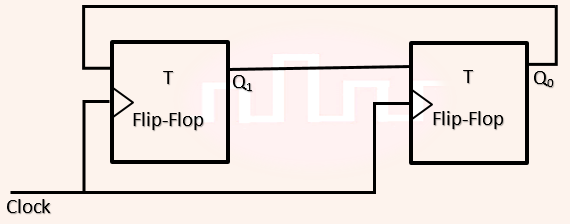 Initially, both Q0 and Q1 are set to 1 (before the 1st clock cycle). The outputs |
| i ➥ Q1Q0 after the 3rd cycle are 11 and after the 4th cycle are 00 respectively |
| ii ➥ Q1Q0 after the 3rd cycle are 11 and after the 4th cycle are 01 respectively |
| iii ➥ Q1Q0 after the 3rd cycle are 00 and after the 4th cycle are 11 respectively |
| iv ➥ Q1Q0 after the 3rd cycle are 01 and after the 4th cycle are 01 respectively |
| Q24➡ | A binary 3 bit down counter uses J-K flip-flops, FF i with inputs Ji , Ki and outputs Qi , i=0,1,2 respectively. The minimized expression for the input from following, is a. J0 = K0 = 0 b. J0 = K0 = 1 c. J1 = K1 = Q0 d. J1 = K1 =Q’0 e. J2 = K2 = Q1 Q0 f. J2 = K2 = Q’1 Q’0 |
| i ➥ a,c,e |
| ii ➥ a,d,f |
| iii ➥ b,c,e |
| iv ➥ b,d,f |
| Q25➡ | Consider the sequential circuit shown in the figure, where both flip-flops used are positive edge-triggered D flip-flops. 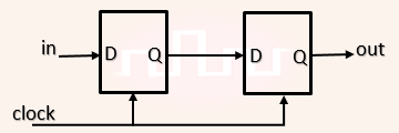 The number of states in the state transition diagram of this circuit that have a transition back to the same state on some value of “in” is ________ |
| i ➥ 2 |
| ii ➥ 3 |
| iii ➥ 4 |
| iv ➥ 5 |
21-i
22-iii
21, ii
22 , ii
23, ii
24,iii
25, iii
Ans21–i
Ans22-iii
Ans23-ii
Ans24-ii
Ans25-i
Ans 21 – 1
Ans 22 – 3
Ans 23 – 2
Ans 24 – 4
Ans 25 – 3
21.i
22.iii
23….
24…..
25……